Brushless DC motor (BLDC Motor) are transforming the landscape of industrial and automation applications, including cradle machines. These motors offer enhanced efficiency, durability, and precision, making them an optimal choice for applications requiring smooth and reliable motion control. Unlike traditional brushed motors, BLDC motors eliminate frictional losses, reduce maintenance requirements, and improve energy efficiency.
A BLDC motor operates using an electronic controller that switches the current to the motor windings in a controlled sequence, ensuring optimal torque and speed. The key components of a BLDC motor include:
Stator: Comprising windings that generate a rotating magnetic field.
Rotor: Embedded with permanent magnets that follow the stator’s magnetic field.
Electronic Controller: Regulates power distribution and ensures synchronized movement.
BLDC motors offer superior control over speed and torque compared to traditional motors, making them ideal for applications that require precision, such as cradle machines.
A Brushless DC motor (BLDC Motor) is a type of 3-phase motor that operates through the magnetic forces of attraction and repulsion between permanent magnets and electromagnets. As a synchronous motor, it runs on direct current (DC) power. This motor is often referred to as a "brushless DC motor" because it eliminates the need for brushes found in traditional DC motors (brushed DC motors or commutator motors). Essentially, a brushless DC motor is a permanent magnet synchronous motor that utilizes DC power input, which is then converted into a three-phase AC power supply with the help of an inverter, along with position feedback to ensure proper functioning.

A brushless DC (BLDC) motor operates based on the Hall effect and consists of several essential components: a rotor, a stator, a permanent magnet, and a drive motor controller. The rotor is equipped with multiple steel cores and windings connected to the rotor shaft. As the rotor rotates, the controller utilizes a current sensor to ascertain its position, enabling it to modify the direction and intensity of the current flowing through the stator windings, which in turn generates torque.
With the aid of an electronic drive controller that oversees the brushless operation and converts the incoming DC power into AC power, BLDC motors can achieve performance comparable to that of brushed DC motors, but without the drawbacks of brushes, which tend to wear out over time. Consequently, BLDC motors are frequently referred to as electronically commutated (EC) motors, setting them apart from conventional motors that depend on mechanical commutation involving brushes.
Brushless DC motors function with two primary components: a rotor embedded with permanent magnets and a stator fitted with copper coils that act as electromagnets when current flows through them.
These motors can be categorized into two types: inrunner (internal rotor motors) and outrunner (external rotor motors). In inrunner motors, the rotor rotates within an externally positioned stator, while in outrunner motors, the rotor spins outside the stator. When current is applied to the stator coils, they create an electromagnet with distinct north and south poles. When the polarity of this electromagnet aligns with that of the adjacent permanent magnet, the like poles repel each other, causing the rotor to turn. However, if the current remains constant, the rotor will only rotate briefly before stopping as the opposing electromagnets and permanent magnets align. To ensure continuous rotation, the current is supplied as a three-phase signal, which regularly changes the polarity of the electromagnet.
The motor's rotational speed is directly related to the frequency of the three-phase signal. To achieve a higher rotation speed, the signal frequency can be increased. For example, in a remote control vehicle, increasing the throttle instructs the controller to elevate the switching frequency, thus accelerating the vehicle.
A Brushless DC motor, commonly known as a permanent magnet synchronous motor, is an electric motor celebrated for its high efficiency, compact design, low noise levels, and extended lifespan. It is widely used in both industrial applications and consumer products.
The operation of a Brushless DC motor relies on the interaction between electricity and magnetism. It consists of key components such as permanent magnets, a rotor, a stator, and an electronic speed controller. The permanent magnets are the primary source of the motor's magnetic field, often made from rare earth materials. When the motor is energized, these permanent magnets establish a stable magnetic field that interacts with the current flowing through the motor, producing a rotor magnetic field.
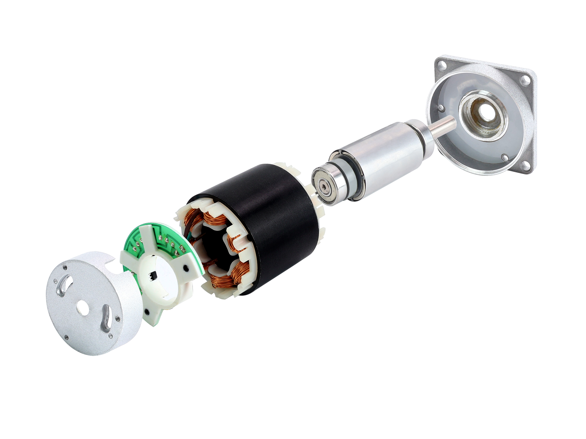
The rotor of a Brushless DC motor is the rotating component and is made up of several permanent magnets. Its magnetic field interacts with the stator's magnetic field, causing it to spin. The stator, on the other hand, is the stationary part of the motor, consisting of copper coils and iron cores. When current flows through the stator coils, it generates a varying magnetic field. According to Faraday's law of electromagnetic induction, this magnetic field influences the rotor, producing rotational torque.
The electronic speed controller (ESC) manages the motor's operational state and regulates its speed by controlling the current supplied to the motor. The ESC adjusts various parameters, including pulse width, voltage, and current, to control the motor's performance.
During operation, current flows through both the stator and rotor, creating an electromagnetic force that interacts with the magnetic field of the permanent magnets. As a result, the motor rotates in accordance with the commands from the electronic speed controller, producing mechanical work that drives the connected equipment or machinery.
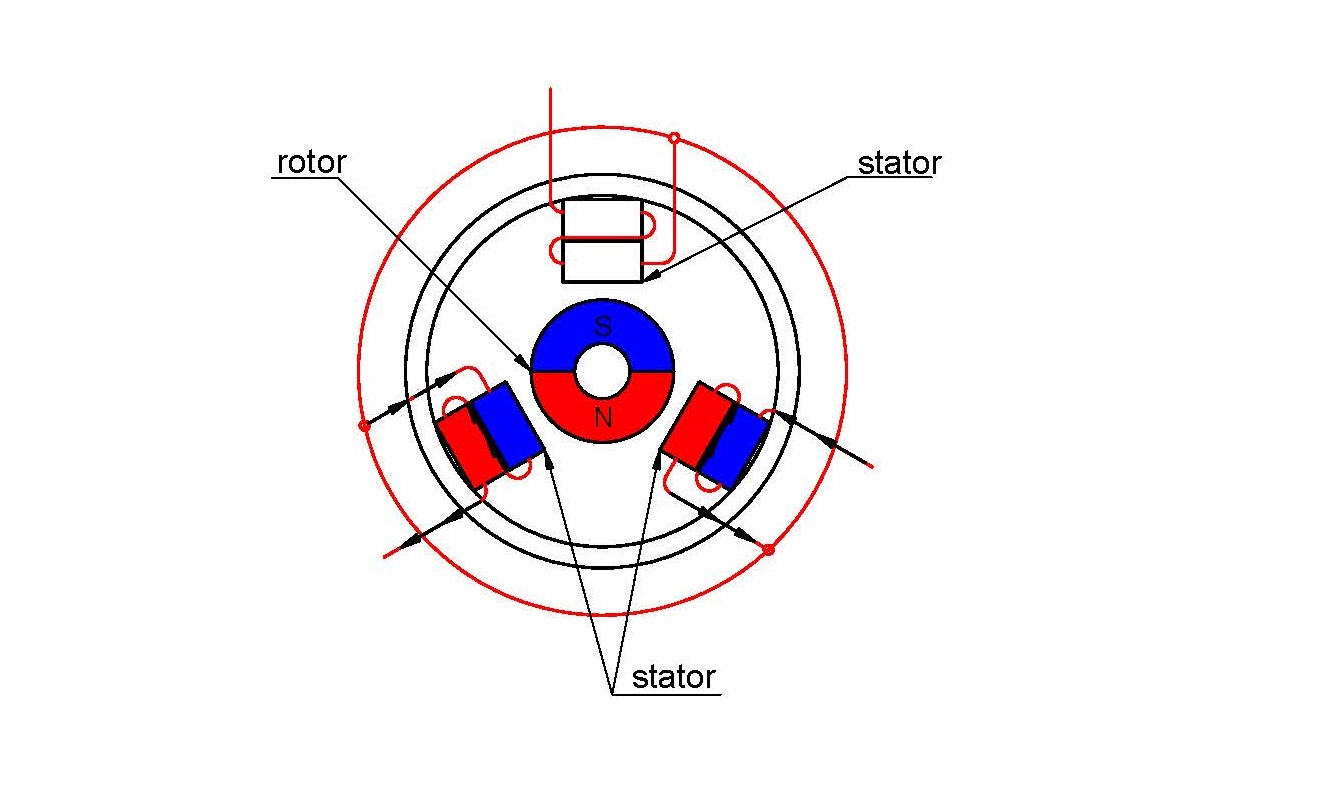
In summary, the Brushless DC motor operates on the principle of electrical and magnetic interactions that produce rotational torque between the rotating permanent magnets and the stator coils. This interaction drives the motor's rotation and converts electrical energy into mechanical energy, allowing it to perform work.
To enable a BLDC motor to rotate, it is essential to control the direction and timing of the current flowing through its coils. The diagram below illustrates the stator (coils) and rotor (permanent magnets) of a BLDC motor, which features three coils labeled U, V, and W, spaced 120º apart. The motor's operation is driven by managing the phases and currents in these coils. Current flows sequentially through phase U, then phase V, and finally phase W. The rotation is sustained by continuously switching the magnetic flux, which causes the permanent magnets to follow the rotating magnetic field generated by the coils. In essence, the energization of coils U, V, and W must be alternated constantly to keep the resultant magnetic flux in motion, thereby creating a rotating magnetic field that continually attracts the rotor magnets.
There are currently three mainstream brushless motor control methods:
Trapezoidal wave control, commonly referred to as 120° control or 6-step commutation control, is one of the most straightforward methods for controlling brushless DC (BLDC) motors. This technique involves applying square wave currents to the motor phases, which are synchronized with the trapezoidal back-EMF curve of the BLDC motor to achieve optimal torque generation. BLDC ladder control is well-suited for a variety of motor control system designs across numerous applications, including household appliances, refrigeration compressors, HVAC blowers, condensers, industrial drives, pumps, and robotics.
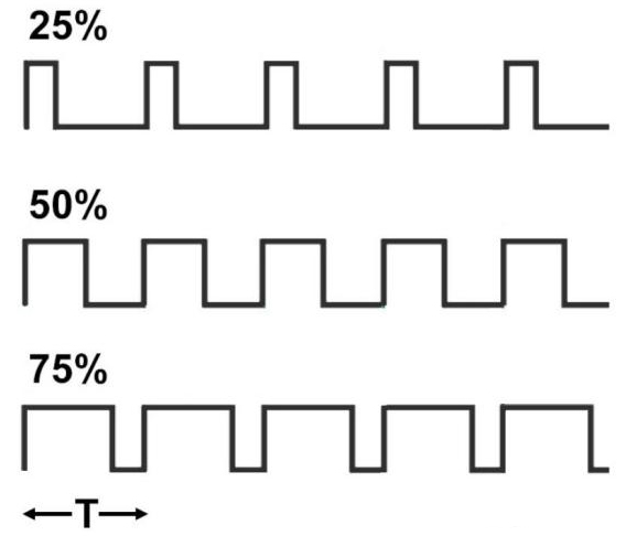
The square wave control method offers several advantages, including a straightforward control algorithm and low hardware costs, allowing for higher motor speeds using a standard performance controller. However, it also has drawbacks, such as significant torque fluctuations, some level of current noise, and efficiency that does not reach its maximum potential. Trapezoidal wave control is particularly suitable for applications where high rotational performance is not required. This method utilizes a Hall sensor or a non-inductive estimation algorithm to determine the rotor's position and executes six commutations (one every 60°) within a 360° electrical cycle based on that position. Each commutation generates force in a specific direction, resulting in an effective positional accuracy of 60° in electrical terms. The name "trapezoidal wave control" comes from the fact that the phase current waveform resembles a trapezoidal shape.
The sine wave control method employs Space Vector Pulse Width Modulation (SVPWM) to produce a three-phase sine wave voltage, with the corresponding current also being a sine wave. Unlike square wave control, this approach does not involve discrete commutation steps; instead, it is treated as if an infinite number of commutations occur within each electrical cycle.
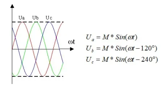
Clearly, sine wave control offers advantages over square wave control, including reduced torque fluctuations and fewer current harmonics, resulting in a more refined control experience. However, it does require slightly more advanced performance from the controller compared to square wave control, and it still does not achieve maximum motor efficiency.
Field-Oriented Control (FOC), also referred to as vector control (VC), is one of the most effective methods for efficiently managing brushless DC motors (BLDC) and permanent magnet synchronous motors (PMSM). While sine wave control manages the voltage vector and indirectly controls the current magnitude, it does not have the capability to control the direction of the current.
.png)
The FOC control method can be viewed as an enhanced version of sine wave control, as it allows for the control of the current vector, effectively managing the vector control of the motor's stator magnetic field. By controlling the direction of the stator magnetic field, it ensures that the stator and rotor magnetic fields remain at a 90° angle at all times, which maximizes torque output for a given current.
In contrast to conventional motor control methods that rely on sensors, sensorless control enables the motor to operate without sensors such as Hall sensors or encoders. This approach utilizes the motor's current and voltage data to ascertain the rotor's position. The motor speed is then calculated based on changes in rotor position, using this information to regulate the motor's speed effectively.
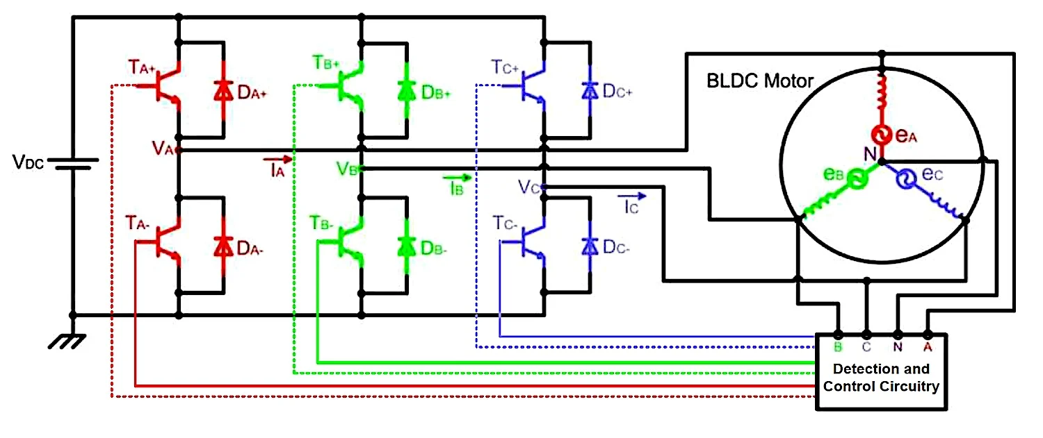
The primary advantage of sensorless control is that it eliminates the need for sensors, allowing for reliable operation in challenging environments. It is also cost-effective, requiring only three pins and taking up minimal space. Additionally, the absence of Hall sensors enhances the system's lifespan and reliability, as there are no components that can be damaged. However, a notable drawback is that it does not provide smooth starting. At low speeds or when the rotor is stationary, the back electromotive force is insufficient, making it difficult to detect the zero-crossing point.
Brushless DC motors and brushed DC motors share certain common characteristics and operational principles:
Both brushless and brushed DC motors have a similar structure, comprising a stator and a rotor. The stator produces a magnetic field, while the rotor generates torque through its interaction with this magnetic field, effectively transforming electrical energy into mechanical energy.
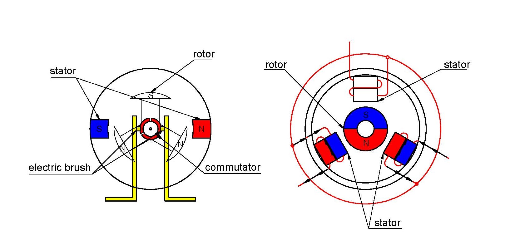
Both Brushless DC motors and brushed DC motors require a DC power supply to provide electrical energy, as their operation relies on direct current.
Both types of motors can adjust speed and torque by altering the input voltage or current, allowing for flexibility and control in various application scenarios.
While brushed and Brushless DC motors share certain similarities, they also exhibit significant differences in terms of performance and advantages. Brushed DC motors utilize brushes to commutate the motor's direction, enabling rotation. In contrast, brushless motors employ electronic control to replace the mechanical commutation process.
There are many types of Brushless DC motor sold by Jkongmotor, and understanding the characteristics and uses of different types of stepper motors will help you decide which type is best for you.
Jkongmotor supplies NEMA 17, 23, 24, 34, 42, 52 frame and metric size 36mm - 130mm standard Brushless DC motor The motors (internal rotor) include 3-phase 12V/24V/36V/48V/72V/110V low voltage and 310V high voltage electric motors with a power range of 10W - 3500W and a speed range of 10rpm - 10000rpm. Integrated Hall sensors can be used in applications that require precise position and speed feedback. While the standard options offer excellent reliability and high performance, most of our motors can also be customized to work with different voltages, powers, speeds, etc. Customized shaft type/length and mounting flanges are available on request.

A brushless DC geared motor is a motor with a built-in gearbox (including spur gearbox, worm gearbox and planetary gearbox). The gears are connected to the drive shaft of the motor. This picture shows how the gearbox is accommodated in the motor housing.
Gearboxes play a crucial role in lowering the speed of brushless DC motors while enhancing the output torque. Typically, brushless DC motors operate efficiently at speeds ranging from 2000 to 3000 rpm. For instance, when paired with a gearbox that has a 20:1 transmission ratio, the motor's speed can be decreased to around 100 to 150 rpm, resulting in a twentyfold increase in torque.
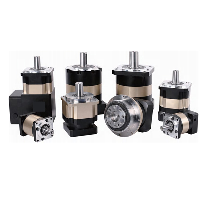
Additionally, integrating the motor and gearbox within a single housing minimizes the external dimensions of geared brushless DC motors, optimizing the use of available machine space.
Recent advancements in technology are leading to the development of more powerful cordless outdoor power equipment and tools. A notable innovation in power tools is the external rotor brushless motor design.
Outer rotor BLDC motors, or externally powered brushless motors, feature a design that incorporates the rotor on the outside, allowing for smoother operation. These motors can achieve higher torque than similar-sized internal rotor designs. The increased inertia provided by external rotor motors makes them particularly well-suited for applications that require low noise and consistent performance at lower speeds.
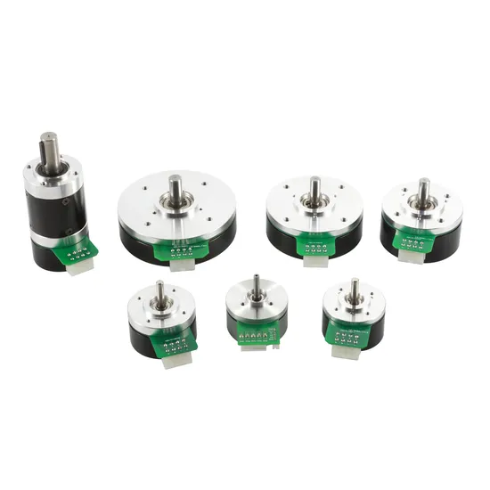
In an outer rotor motor, the rotor is positioned externally, while the stator is situated inside the motor.
Outer-rotor BLDC motors are typically shorter than their inner-rotor counterparts, offering a cost-effective solution. In this design, permanent magnets are affixed to a rotor housing that revolves around an inner stator with windings. Due to the higher inertia of the rotor, outer-rotor motors experience lower torque ripple compared to inner-rotor motors.
Integrated brushless motors are advanced mechatronic products designed for use in industrial automation and control systems. These motors come equipped with a specialized, high-performance brushless DC motor driver chip, providing numerous advantages, including high integration, compact size, complete protection, straightforward wiring, and enhanced reliability. This series offers a range of integrated motors with power outputs from 100 to 400W. Furthermore, the built-in driver utilizes cutting-edge PWM technology, allowing the brushless motor to operate at high speeds with minimal vibration, low noise, excellent stability, and high dependability. Integrated motors also feature a space-saving design that simplifies wiring and reduces costs compared to traditional separate motor and drive components.
Advantages of Using BLDC Motors in Cradle Machines
BLDC motors are highly efficient due to their electronic commutation system, reducing power losses and ensuring lower energy consumption. This feature makes them a sustainable choice for cradle machines operating continuously.
Unlike brushed motors, BLDC motors do not experience wear and tear due to the absence of brushes. This eliminates frequent maintenance, extends the motor’s lifespan, and ensures uninterrupted performance.
The electronic controller allows for precise speed and torque adjustments, enabling cradle machines to operate with consistent motion and minimal vibrations. This precision is crucial for applications requiring delicate handling.
The absence of brushes minimizes mechanical noise, making BLDC motors significantly quieter than conventional brushed motors. This is essential for applications where noise reduction is a priority.
Selecting a BLDC motor with the appropriate power rating ensures optimal performance and energy efficiency. The power rating should align with the specific needs of the cradle machine to avoid overloading or inefficiencies.
Understanding the operational speed and torque of the cradle machine is critical. High-torque BLDC motors are recommended for applications requiring steady motion and load-bearing capabilities.
Matching the voltage and current ratings of the BLDC motor with the machine's power supply prevents compatibility issues and ensures stable operation.
The electronic controller should be compatible with the cradle machine’s control system to facilitate seamless integration and optimal performance.
BLDC motors are widely used in various industrial, medical, and automation applications. In cradle machines, they play a crucial role in:
Automated Baby Cradles: Ensuring smooth and silent rocking motions for enhanced comfort.
Industrial Cradle Mechanisms: Providing consistent and controlled movement for specialized applications.
Medical Cradles and Equipment: Enabling precision motion in sensitive environments.
The adoption of BLDC motors in cradle machines offers unparalleled benefits, including energy efficiency, longevity, precision, and low noise operation. As industries continue to seek reliable and high-performance solutions, BLDC motors remain the preferred choice for modern cradle machine applications.
View More(Total0)Comment Lists